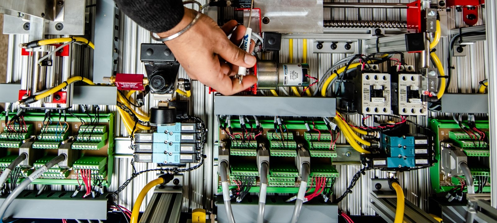
PLC Hardware Components
The PLC's input/output (I/O) section links all field devices to the CPU and acts as an interface between them and the CPU. The input/output configuration of a fixed PLC is built in, whereas modular PLCs use extra I/O modules that connect to the PLC. Figure 2-1 depicts a rack-based I/O section made up of individual I/O modules. Input interface modules accept signals from machines or process devices and convert them to signals understandable by the controller. Output interface modules convert controller signals into external signals that can be used to control a machine or process.

A conventional PLC has room for multiple I/O modules, allowing it to be tailored to a given application by selecting the appropriate ones. Any type of I/O module can be put in any rack slot. The I/O system connects the CPU to the hardwired components in the field. The input interface allows the CPU to receive status information about processes, and the CPU may then send operational signals to the process devices under its control via the output interface.
The I/O modules in a PLC system can be located near to the field devices, as shown in Figure 2-2, minimizing the amount of cable required. The processor receives signals from remote input modules and sends them to the appropriate output modules via the communication module.
A rack is referred to be a distant rack when it is located far away from the processing module. The remote rack communicates with the CPU through a separate communications network. A unique station number is required to distinguish one remote rack from another. The remote racks are linked to the local rack through a communications module. The modules are connected via wires.

I/O points can be operated from more than 20 miles away with minimal voltage loss using a fiber optic link between the CPU and the I/O rack. Coaxial wire can be used to establish remote I/O across lengths of up to two miles. Noise caused by neighboring high-voltage lines or industrial equipment will not be picked up by fiber optic cable. This type of noise is more sensitive to coaxial cable.
The PLC's memory system stores information about the state of all inputs and outputs. To keep track of all of this data, it uses a method known as addressing. An address is a label or number that indicates where a certain piece of data is kept in a PLC's memory. The address of a device or a piece of data indicates where information about it lives in the PLC's memory, just like your street address indicates where you live in your city. As a result, when a PLC requires information from a field device, it learns to look in the right area.
Allen-Bradley SLC 500 controllers employ rack/slot-based addressing schemes, Allen-Bradley ControlLogix controllers use tag-based addressing schemes, and soft PLCs use PC-based control.
Examples of rack/slot-based addressing components include:
The type determines whether the address is to an input or an output.
Slot - The slot number indicates the physical location of the I/O module. When using extension racks, this might be a combination of the rack number and the slot number.
Word and Slot— The word and slot of an I/O module are used to identify the actual terminal connection. A discrete module generally uses just one word, with each connection matching to a unique bit in the word.
In a rack/slot address system, the address of an input or output device is defined by the position of a module inside a rack and the terminal number of a module to which it is coupled.
Figure 2-3 depicts the rack/slot addressing format of the Allen-Bradley SLC 500 controller. The address is used by the CPU to determine where the device is located in order to monitor or operate it. There are additionally many connectors for field wiring on the I/O module housing. When changing modules, the field wiring is attached to the I/O housing, making it simple to detach and rejoin the wire. Each module also features LEDs that indicate whether each I/O circuit is turned on or off. The majority of output modules also provide blown fuse alerts. Some frequent real-world SLC 500 generic input and output addresses are as follows:

The input and output devices of a discrete I/O module are each allocated to a different bit in the PLC's memory.
A bit is a binary digit with one of two possible values: one or zero. Analogue I/O modules employ word addressing, which allows the entire word to be addressed. The bit component of the address is rarely used; nevertheless, if required, the programmer may address bits of the digital version of the analogue value. Figure 2-4 demonstrates how to use an SLC 500 to address a controller at the bit and word levels.


Tag-based memory architectures are the most recent type of PLC memory addressing. Figure 2-5 depicts the tag-based addressing format used by Allen-Bradley ControlLogix and CompactLogix. Memory locations are specified using the base and alias tags. A base tag identifies a memory space for data storage. An alias tag is used to change the name of a tag (alias). The alias tag is widely used when constructing a tag name to represent a real-world input or output.

Figure 2-5 Allen-Bradley ControlLogix tag-based addressing format. Source: Image Courtesy of Rockwell Automation, Inc.
Figure 2-6 depicts a comparison between rack/slot-based and tag-based addressing. When setup, input and output modules generate their own tags such as Local: 1:I.Data.1. Tag names describe the data that is contained in them. The alias tag allows you to utilize names that are more relevant to the application. In this case:
• Pressure switch is used rather than I:1/1.
• Instead of I:1/2, temperature switch is used.
• Instead of I:1/3, manual pushbutton is used.
• O:2/1 is replaced with Mixer motor.

Personal or industrial hardened computers are used for PC-based control. Soft PLCs, as they are often known, imitate the functionality of a PLC on a PC, allowing open architecture solutions to replace proprietary PLCs. As an interface for the field devices, this version employs an input/output card (Figure 2-7) in combination with the PC.

Combination I/O As shown in Figure 2-8, modules can contain both input and output connections in the same physical module. A printed circuit board and a terminal assembly comprise a module. The printed circuit board houses the electrical circuitry that connects the processor's circuit to the input or output device's circuit. Modules are intended to be inserted into a slot or connection in the I/O rack or directly into the CPU. The terminal assembly, which is affixed to the printed circuit board's front edge, is utilized to make field-wiring connections.

Modules have terminals for each input and output connection, status LEDs for each input and output, and power supply connectors. Different manufacturers have different configurations for terminal and status lights. The wiring terminal strips on most PLC modules are plug-in. As shown in Figure 2-9, the terminal block is inserted into the real module. If a module fails, the entire strip is unplugged, a new module is installed, and the terminal strip is hooked into the new module.

Never install or remove I/O modules or terminal blocks while the PLC is switched on, unless otherwise indicated. Incorrect voltages supplied through the wire arm might harm a module put in the incorrect slot. Most faceplates and I/O modules are keyed to prevent the wrong faceplate from being installed on the wrong module. In other words, an output module cannot be installed in the same slot as an input module.
Input and output modules can be placed anywhere in a rack, however they are usually clustered together to make wiring easier. I/O modules are available in 8, 16, 32, and 64 point configurations (Figure 2-10). The number denotes the number of available inputs or outputs. The typical I/O module has eight inputs and eight outputs. A high-density module can contain as many as 64 inputs and outputs. The high-density module has the advantage of allowing you to add up to 64 inputs or outputs in one slot, saving you space. The sole downside is that high-density output modules cannot take as much current per output as low-density output modules.

Next Post is " Direct I/O Modules & Analog I/O Modules"


0 Comments