Principles of Operation
To understand how a PLC works, consider the simple process control problem depicted in Figure 1-16. A mixer motor will automatically swirl the liquid in a vat when the temperature and pressure reach predefined values. A separate pushbutton station also provides for direct human control of the motor. Temperature and pressure sensor switches are used to monitor the process and stop their connections when the conditions reach their specified thresholds.


Consider how a programmable logic controller may be used in this circumstance. As input field devices, the same pressure switch, temperature switch, and pushbutton are used. These devices would be linked to an appropriate input module using the manufacturer's addressing placement mechanism. The wiring connections for a 120 VAC modular configuration input module are shown in Figure 1-18.

The output field device would be a motor starting coil. This device would be linked to an appropriate output module using the manufacturer's addressing placement mechanism. The wiring connections for a 120 VAC modular adjustable output module are shown in Figure 1-19.

After that, the PLC ladder logic program would be produced and saved in the CPU's memory. A example ladder logic program for this technique is shown in Figure 1-20. The arrangement is similar to a hardwired relay ladder circuit. Individual symbols represent instructions, whereas numbers represent instruction location addresses.
To program the controller, insert these instructions from the programming device into the processor memory one at a time. Each input and output device is given an address, which tells the PLC where it is physically located. It's important to note that the I/O address format changes depending on the PLC type and manufacturer. Instructions are stored in the user program portion of the processor memory. During the program scan, the controller monitors the inputs, executes the control program, and alters the output accordingly.
In order for the program to operate, the controller is set to RUN mode, or operational cycle. During the program scan, the controller monitors the inputs, executes the control program, and alters the output accordingly. Each -I I- symbol (which looks like an open contact) conveys a command.
The -()- symbol is considered to represent a coil that, when triggered, energizes the device attached to the proper output. When contacts I/1 and I/2 are closed, or when contact I/3 is closed, the coil O/1 is lit in Figure 1-20's ladder logic program. Either of these criteria leads in a logic path that spans the rung from left to right, including the coil.

A programmable logic controller (PLC) functions in real time, which means that an occurrence in the field causes an action or output to be performed. The RUN operation for the process control system may be defined by the following sequence of events:
• First, the controller's memory is verified to see if the pressure switch, temperature switch, and pushbutton inputs are operational.
• In memory, a closed contact is recorded as logic 1, whereas an open contact is stored as logic 0.
• The ladder diagram is then evaluated, and each internal contact is assigned an OPEN or CLOSED status depending on its recorded 1 or 0 state.
• The ladder diagram is then evaluated, and each internal contact is assigned an OPEN or CLOSED status depending on its recorded 1 or 0 state.
• When the states of the input contacts maintain logic continuity from left to right across the rung, the output coil memory location is assigned a logic 1 value and the output module interface contacts close.
• If there is no logic continuity in the program rung, the output coil memory location is set to logic 0 and the output module interface connections are open.
• When the controller completes one cycle of this sequence, a scan happens. The scan time, or the amount of time it takes to complete one full cycle, is a measure of the PLC's reaction speed.
• The output memory address is frequently altered during the I/O scan, but the actual output is not updated until the program scan is completed.
Figure 1-21 depicts the typical wiring required to implement the process control strategy with a fixed PLC controller. In this example, the Allen-Bradley Pico controller with 8 inputs and 4 outputs is used to control and monitor the process. The installation is summarized as follows:

• The controller's L1 and L2 terminals are linked to fused power lines of the requisite voltage type and level.
• Pressure switches, temperature switches, and pushbuttons are linked between L1 and the controller input terminals I1, I2, and I3, respectively.
• The motor starter coil is connected directly to L2, and the Q1 relay output contacts are linked in series to L1.
• To input the ladder logic program, utilize the front keypad and LCD display.
• Pico programming software is now available, allowing you to develop and test your program on a computer.
Modifying the PLC Operation
One of the most important advantages of a PLC is the ease with which its software may be modified. Assume that the original process control circuit for the mixing operation has to be changed, as indicated in the relay ladder design in Figure 1-22. The manual pushbutton control must now be permitted to function at any pressure, but only when the specified temperature is satisfied.

Figure 1-22 Relay ladder diagram for the modified process.
Some rewiring of the circuit indicated in Figure 1-22 would be required to make the necessary alteration using a relay system. However, if a PLC system is used, no rewiring is necessary. The inputs and outputs are unaltered. All that is required is a few adjustments to the PLC ladder logic program, as shown in Figure 1-23.

Figure 1-23 PLC ladder logic program for the modified process.
Computers vs. PLCs
The architecture of a PLC is substantially comparable to that of a personal computer. A programmable logic controller can be employed if you provide a way for the computer to take information from devices such as pushbuttons or switches. You'll also need software to understand the data and a way to turn devices on and off.
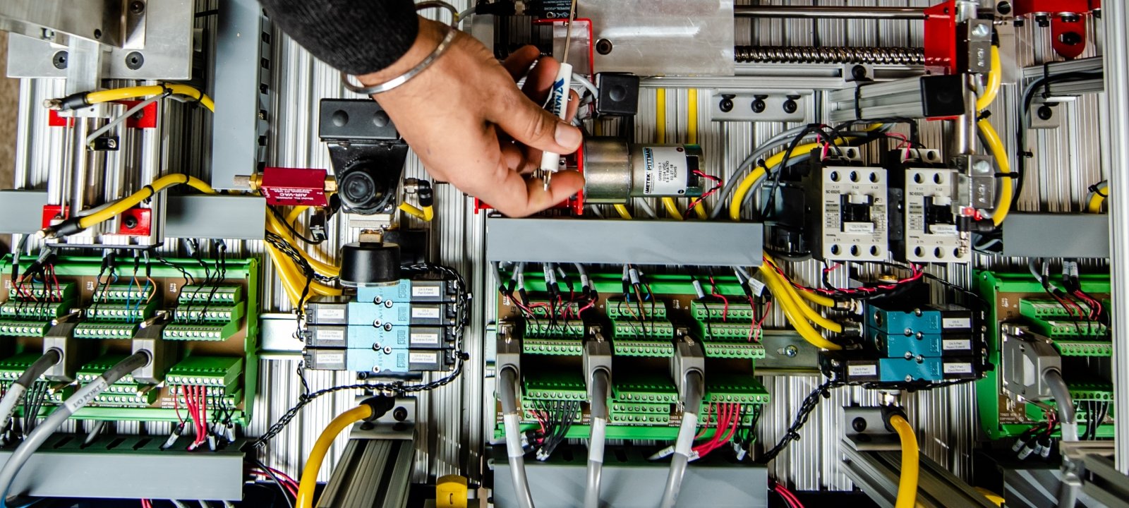
PLCs, on the other hand, have a few important characteristics that distinguish them from personal computers. To begin, unlike PCs, PLCs are designed to operate in an industrial context with a wide range of ambient temperature and humidity. Electrical noise is rarely an issue in most industrial sites for a well-designed industrial PLC system, such as the one represented in Figure1-24.

Terminals for input and output field devices, as well as communication ports
Computers are complex computing machines that can execute several programs or activities at the same time and in any order. Most PLCs, on the other hand, run a single program logically and sequentially from start to finish.
PLC control systems are designed to be easy to install and maintain. The addition of fault signals and alerts shown on the programmer screen simplifies troubleshooting. It is simple to connect and replace input/output modules for field equipment.
The two primary kinds of software connected to a PLC but produced and controlled on a personal computer are as follows:
• Programmable logic controller (PLC) software that allows users to program and document provides users with the tools they need to write a PLC program (using ladder logic or another programming language) and document or explain it in as much detail as they require.
• A human machine interface (HMI) is a piece of PLC software that allows the user to monitor and control the process (HMI). It enables the user to monitor a process (or a graphical representation of a process), assess how the system is operating, trend figures, and receive alarm conditions (Figure 1-25). Many operator interfaces do not employ PLC software. Despite the fact that PLCs and HMIs can be connected, the software required to program both devices is not the same.


PLC Size and Applications
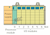
The functionality, number of inputs and outputs, cost, and physical size of PLCs are used to classify them (Figure 1-27). The I/O count is the most important of them. Nano is the smallest size, with often less than 15 I/O points. The following three categories are micro (15 to 128 I/O points), medium (128 to 512 I/O points), and large (above 512 I/O points). The compatibility of the PLC with the application is an important element in the selection process.

Figure 1-27 Typical range of sizes of programmable controllers.
PLC applications are classified into three types: single ended, multipurpose, and control management. In a single-ended or stand-alone PLC application, one PLC controls one process (Figure 1-28). This would be a stand-alone device, not linked to any other computers or PLCs. When selecting a PLC, the size and complexity of the process to be managed are obvious concerns. Although the applications may call for a strong CPU, this category often calls for a modest PLC.
In a multitask PLC application, one PLC controls many operations. Enough I/O capacity is necessary in this type of configuration. A data communications network is also required if the PLC is part of a bigger operation and has to communicate with a central PLC or computer.

In a control management PLC application, one PLC controls numerous others (Figure 1-29). This application requires a large PLC processor that can communicate with other PLCs as well as a computer.
The control management PLC supervises a large number of PLCs by downloading programmes that instruct the other PLCs on what they must perform.
It must be able to connect to all PLCs in order to interact with anybody it chooses using suitable addressing.
The memory of a PLC stores data, instructions, and the control software. Memory sizes are frequently expressed in K numbers, such as 1 K, 6 K, 12 K, and so on. The kilo, abbreviated K, is a measuring unit that normally equals 1000 units.
However, because this measurement is based on the binary number system, when dealing with computer or PLC memory, 1 K represents 1024. (210 5 1024).

The amount of RAM required depends on the program. The memory amount required for a certain PLC installation is influenced by the following factors:
• The total number of I/O points used
• The control program's scope
• Data collecting requirements
• Supervisory functions are required.
• Possibility of future expansion


 Principles of Operation)
0 Comments