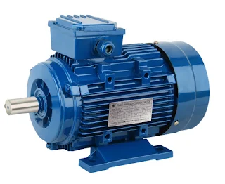
Induction Motor :
The motor controls the kinetic energy and the torque from the air in the beginning to overcome the moment of inertia of the load and the mechanic. This ratio varies from one type to another, and this current is possible for the single current in that it cannot withstand the resulting temperature as is the case for the resulting values, which leads to its rise The result is the effort.
Configuration of the induction motor:
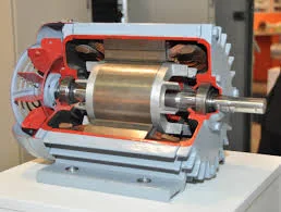
The motor consists of two ends, one of which is static and called (stator) and the other is rotating, called (rotor), and the speed of rotation is related to the value of the frequency of the current in the circuit. Between the rotor and the stator there is a distance of air called the air gap, and the smaller the distance between the rotor and the stator, the lower the value of the air resistance.
Working principle of induction motor:
The alternating current flows from the side of the stationary body (the stator) connected to the source of the alternating voltage, and the current passes through its coils. This flux takes place in the magnetic circuit that is formed between the stator and the rotor - where there is no electrical connection between them - and when a magnetic flux passes through the coils of the rotor (Rotor) it induces an electric current in the electrical circuit according to (Fraday's law), resulting in The movement of current and flux is a rotating magnetic field that rotates the secondary terminal.
How is a rotating magnetic field formed?
When connecting an electrical source (3 phase), meaning that between each face and the other 120 degrees of electricity and the stator coils, the angle between each coil and the other is 120 degrees, so balanced currents will pass between each current and the other 120 degrees, creating a uniform magnetic field and this The field rotates at a synchronous speed, which is calculated from the following equation:
Ns=120Fs/p
Ns: Synchronous speed.
Fs: the frequency of the stator current.
p: the number of electrodes.
slip:
When the rotor rotates at a speed of N revolutions per minute, the relative velocity between the rotating magnetic field at the synchronization speed Ns and the coils of the rotating member is (Ns-N), and it is called the slip speed and is symbolized by the symbol (S) and its value ranges in Small engines range between 1% or 2%, and in large engines, it reaches 0.5% in the case of no load and in the case of loading.
Slippage ranges from 3% to 5% and is calculated from:
Slip Speed = Nslip = Ns-N
Slip =S =Ns-N/Ns
So it can be said that slip is a relationship between the speed of the rotor speed and the synchronization speed, and the difference in speed depends on the load, and the speed of the rotating member must be less than the synchronization speed.
Note that the value of slip is zero when the rotating member rotates at the same synchronous speed
(N = Ns) and is equal to one when the rotating member is at rest (N = 0).
To find out the speed of the rotor member (Rotor Speed) = N = Ns(1-S)


0 Comments