AC Motors
What is an AC Motors?
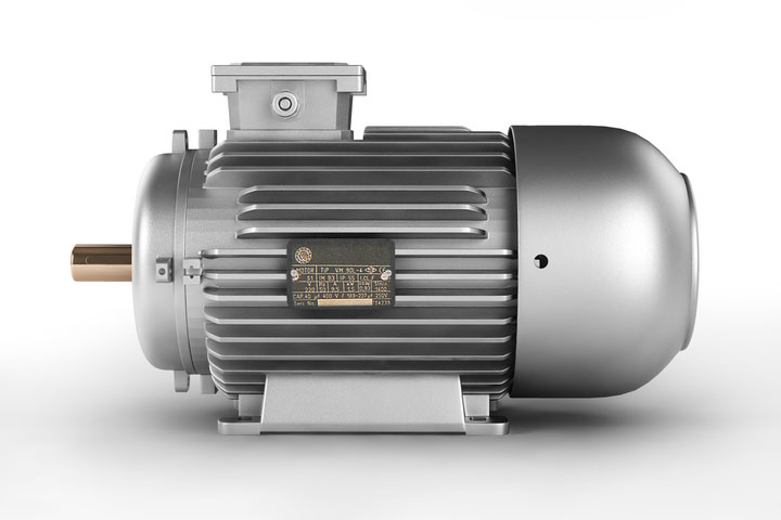
- A motor that transforms alternating current into mechanical power is known as an AC motor. The stator and rotor are critical components of AC motors. The stator is the motor's fixed component, while the rotor is the motor's spinning component. Single-phase or three-phase AC motors are available.
- AC motors are utilized in a variety of residential, commercial, industrial, and utility applications all around the world. Electrical energy is converted into mechanical energy by motors.
- An AC motor can be a part of a pump or fan, or it can be coupled to other mechanical equipment like a winder, conveyor, or mixer.
- AC motors are used in a wide range of applications, from those that only require a single motor to those that require several motors.
AC Motor Construction
The AC motor is powered by alternating current. AC motors are made up of two major components: a stationary stator and a revolving rotor. Let's look at the components of an AC motor in this section.
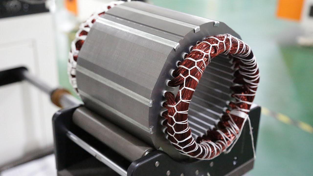
Stator winding
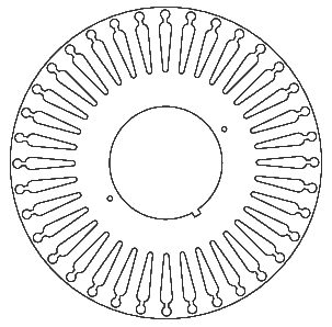
- A hollow cylinder is formed by stacking stator laminations together. Insulated wire coils are placed into stator core slots.
- The stator is the motor's stationary component that transmits a revolving magnetic field to the rotor.
- An electromagnet is made up of a collection of coils that surrounds a steel core. The operation of a motor is based on electromagnetism. The power supply is directly linked to the stator windings.
Rotor Construction
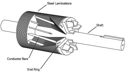
The rotor is the component of the electromagnetic circuit that rotates. The “squirrel cage” rotor is the most popular form of rotor.
The rotor is the moving component of an electric motor, and its primary function is to spin the shaft in order to generate mechanical power. The rotor, in general, is made up of conductors that transport current and interact with the stator's magnetic field.

A rotor core is formed by stacking the laminations together. Aluminum is die cast into the rotor core's slots, forming a series of conductors around the rotor's circumference. With end rings, the conductor bars are mechanically and electrically linked. To construct a rotor assembly, the rotor core is mounted on a steel shaft.
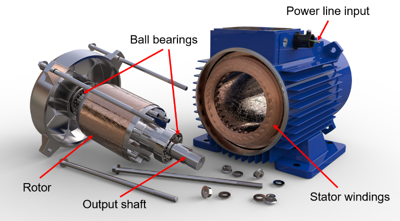
Motor Enclosure
A frame (or yoke) and two end brackets make up the enclosure (or bearing housings). Inside the frame is where the stator is installed. With a little air gap between the rotor and the stator, the rotor fits within the stator. The rotor and the stator do not have a direct physical connection.
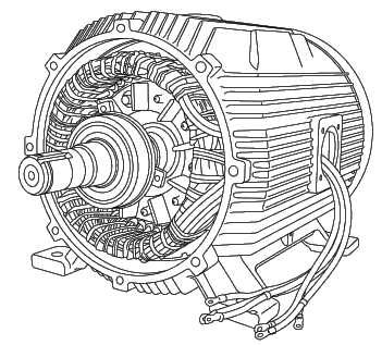
The motor's electrical and operational elements are additionally protected from the detrimental effects of the environment in which it runs by the enclosure. The rotor is supported and rotates by bearings placed on the shaft. The motor pictured below has a fan for cooling, which is likewise placed on the shaft.
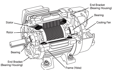
- End bracket: At the shaft end of the electric motor, the end bracket is attached to the frame, providing a way to secure the device as well as an aperture for the shaft to pass through.
- Bearing: The motor's bearings primarily provide support for the rotor in order for it to activate its axis. The shaft of the motor expands to the load of the motor with the aid of the bearings. The load is termed as overhung when the load forces are applied outside of the bearing.
- Frame (York): This is the container that holds all of the electric motor's numerous component
Classification of A.C Motor
AC motors are classified as follows, based on their operation principle:
- Induction Motor
- Synchronous Motor

An Induction Motor's Basic Operating Principle.
Before we go into this section, let's have a look at the Electrical Principle.
Electrical Principle
At its most basic level, electricity is defined as the passage of an electrical charge. In its most basic form, a direct current (DC) circuit consists of an electrical source connected to one of the source terminals by a conducting wire and another conducting wire connected to the other source terminal by another conducting wire.
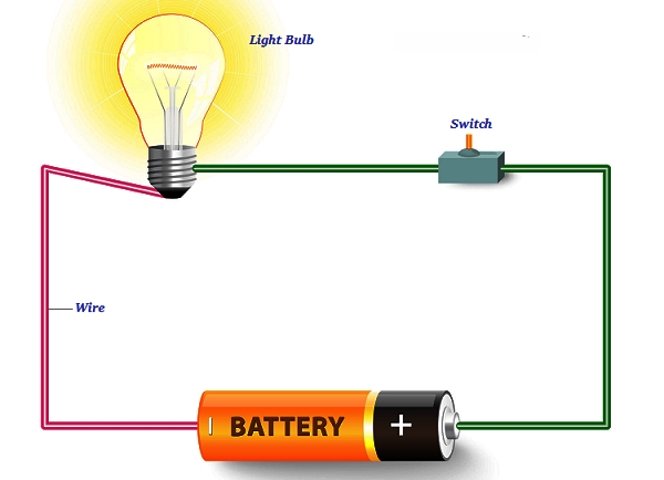
The simplest basic DC circuit is a battery connected to a light bulb. Charge passes from one battery terminal to the next, via the lightbulb (lighting it up), and then back to the first. When the circuit is broken, the flow stops and the bulb stops shining.
Electrical current is defined as the amount of charge flowing through a component in a given length of time, measured in Amps (Amperes in full, SI symbol A). The circuit's resistance is measured in Ohms (SI symbol), which is equivalent to electrical friction.
Voltage is the pressure that drives current through a circuit and is measured in Volts (SI symbol V). According to Ohm's law, the voltage in Volts is always the product of the current in Amps and the resistance in Ohms.
Watts (SI symbol W) are a unit of measurement for the rate at which electric energy is transferred, and they are calculated by multiplying the voltage in Volts by the current in Amps.
As a result, there are two main equations to consider:
- Volt = current x resistance. V= I x R (v)
- Active Power = Volt x Current. P= V x I (Watt)
Operating a Simple Motor
The following diagram shows the simplest basic DC motor, which is made up of a wire coil positioned on a pivot that allows it to rotate. The coil's two ends are connected to two sides of a commutator, which rotates in the same direction as the coil. Brushes connect the commutator to a power source (in this case, a battery) and allow electrical current to flow as it rotates.
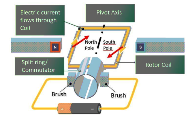
A magnetic field is created when electrical current passes through the rotor coil, resulting in the formation of north and south magnetic poles on opposing sides of the coil. Meanwhile, two permanent magnets are positioned at the sides of the rotor coil, their poles opposing the magnetic poles induced in the rotor coil, causing the rotor poles to be repelled by the fixed magnets.
As a function of the repulsion, the rotor will begin to circle on its axis. The rotor would rotate 180 degrees before halting due to magnetic attraction when the rotor poles met the fixed magnets' opposing magnetic poles if all other conditions were equal.
Due to the commutator and brushes arrangement, as the rotor coil spins, the ends of the coil become attached to the opposing terminals of the battery, and the current flowing through the rotor coil changes direction and the sides of the coil exchange polarity. The coil and fixed magnet poles repel each other once more, and the rotor spins on its axis.
The rotor continues to revolve, propelled by the repelling fixed magnets, while the poles are pushed past each other by the rotating coil's velocity.
A.C. Alternating Current
Alternating current is easier and cheaper to generate and, more crucially, transfer, the electricity we get through grid supply networks is in this form (AC).
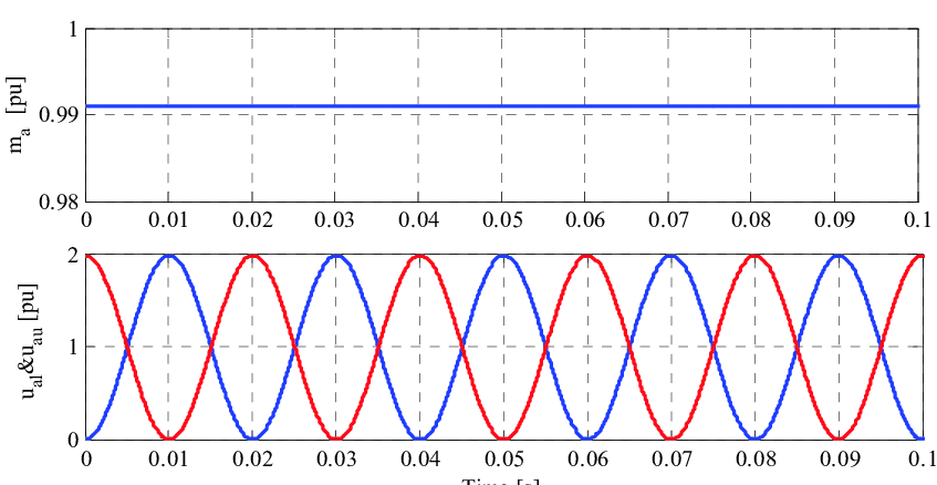
The voltage in an AC waveform fluctuates throughout time, alternating between positive and negative values, unlike in DC. In one full cycle, the voltage varies from zero to maximum, zero to minimum, and back to zero; the frequency, measured in Hertz, is the number of such cycles each second (SI symbol Hz). Almost 90% of the world's electrical power is delivered at a 50Hz or 60Hz frequency.
AC Induction Motors
The induction motor is a motor that operates on the concept of electromagnetic induction. Electromagnetic induction occurs when an electrical conductor is put in a rotating magnetic field and the electromotive force induces across the conductor.
Coils of insulated wire are positioned in the Stator slots in the casing of a three-phase AC induction motor. When energized, each of the three electrical phases (U-V-W) is represented by a set of electromagnetic poles.
Figure 1 depicts a motor with coils organized in such a way that each phase contains a pair of poles (labelled U1 and U2, V1 and V2, W1 and W2). This is referred to as a two-pole configuration since each phase has two poles; if each phase has two pairs of poles, it is referred to as a four-pole configuration, and so on.
When the coils of the Stator are linked to an AC source, an electrical current flows through them, producing a magnetic field - the coils are coiled with opposing polarity poles in each pair.
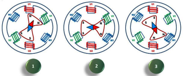
Fig,1 A 3-phase AC induction motor's cyclical rotating magnetic field
The magnetic field rotates around the center axis of the Stator due to the cyclical nature of the AC waveform, with two north and two south poles at any one moment. The number of pairs of poles and the electrical supply frequency (50Hz or 60Hz - see ‘Motors Basic Part One') determine the rotational speed.
When one pair of poles is present, the magnetic field spins once per electrical cycle; when two pairs are present, the magnetic field rotates once every two cycles; and when three pairs are present, the magnetic field rotates once every three cycles.
The following is the basic equation for determining Synchronous Speed:
Synchronous Speed (rev/min) = Supply Frequency (Hz) x 120
Number of poles for each phase
So, if the motor in Figure 1 is powered by a 50Hz source, the synchronous speed is:
As a result, the larger the number of poles, the slower the synchronous speed - a motor with 12 poles per phase, for example, would have a synchronous speed of just 500 rev/min.
The Rotor
The Rotor, together with the Stator, is the most essential component of an AC induction motor. This is made up of rotor bars, which are generally made of aluminum or copper, and are connected to rings made of the same material at their ends. This rotor is commonly referred to as a 'Squirrel Cage' Rotor (see Figure 2).

A ‘Squirrel Cage' rotor is shown in Figure 2.
Because the voltage in the Rotor bars is created by the Stator's magnetic field cutting through them, if the Rotor rotates at a synchronous speed, there will be no relative movement between the Rotor bars and the Stator magnetic field, and no voltage will be induced in the Rotor bars.
When a load is given to the Rotor, it begins to slow down, causing it to interact with the Stator magnetic field, resulting in torque production as seen in Figure 2. The load supplied to the Rotor will be driven by that torque.
Synchronous speed is determined by the frequency of the electrical supply and the winding arrangement of the Stator (number of poles). Slip is the difference between synchronous and Rotor speeds; it is stated as a percentage of synchronous speed and may be computed using the following equation:
Slip = Synchronous Speed – Rotor Speed
Synchronous Speed
Visit this site to learn how to control an induction motor.


0 Comments